
BROCHURE
Contact YPT for a detailed information about YPT DCP SERIES CARBON PUMPS .
YPT Quality Management System
For detailed information about YPT Quality Management System
YPT POMPA Slurry Pumps Factory
For detailed information about YPT POMPA Slurry Pumps Factory
Non-clogging carbon transfer for tough process conditions
YPT DCP SERIES — VERTICAL CARBON PUMPS
The DCP Series is a vertical carbon pump designed for duties where clogging risk must be engineered out, not managed operationally.
It is typically applied where solids can be large relative to the pipe size and where stable transfer is required without frequent intervention.
The hydraulic concept centers on a recessed, cup-type impeller that keeps the main flow path open and tolerant to solids.
Durability is reinforced through an extra-thick impeller design intended to resist erosion and preserve hydraulic geometry over time.
Selection is usually driven by solids passage requirements, reliability targets, and the need for predictable long-run performance.
It is typically applied where solids can be large relative to the pipe size and where stable transfer is required without frequent intervention.
The hydraulic concept centers on a recessed, cup-type impeller that keeps the main flow path open and tolerant to solids.
Durability is reinforced through an extra-thick impeller design intended to resist erosion and preserve hydraulic geometry over time.
Selection is usually driven by solids passage requirements, reliability targets, and the need for predictable long-run performance.


Carbon forwarding with clogging engineered out
Typical duties
DCP pumps are selected for carbon circuit services where continuous transfer matters more than chasing marginal efficiency gains.
These duties often run in tight operating windows, so unexpected stoppages can impact adsorption performance, screen loading, and overall circuit stability.
Many carbon transfer lines also see solids that can bridge or hang up in conventional impeller passages, especially during upset conditions.
A vertical configuration is often preferred where floor space is limited or where the pump must integrate directly into a tank or pit layout.
For these reasons, DCP is positioned primarily for the following duty family.
These duties often run in tight operating windows, so unexpected stoppages can impact adsorption performance, screen loading, and overall circuit stability.
Many carbon transfer lines also see solids that can bridge or hang up in conventional impeller passages, especially during upset conditions.
A vertical configuration is often preferred where floor space is limited or where the pump must integrate directly into a tank or pit layout.
For these reasons, DCP is positioned primarily for the following duty family.
Recessed cup impeller keeps passages open
Core design features
The DCP platform is built around two practical priorities: keep solids moving, and keep wear predictable. In carbon duties, reliability is often defined by “no surprises,” meaning the pump must avoid clogging events that force unplanned shutdowns.
The recessed cup-type impeller approach supports that by minimizing internal obstruction points where solids can accumulate.
Durability is further supported through a thick impeller rim and vane geometry designed to resist erosion and maintain its hydraulic shape for longer service intervals.
The result is a configuration intended to run consistently with fewer adjustments and fewer interventions during its normal wear life.
The recessed cup-type impeller approach supports that by minimizing internal obstruction points where solids can accumulate.
Durability is further supported through a thick impeller rim and vane geometry designed to resist erosion and maintain its hydraulic shape for longer service intervals.
The result is a configuration intended to run consistently with fewer adjustments and fewer interventions during its normal wear life.
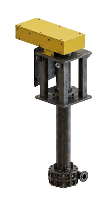
Open flow path for pipe-sized solids
Principle of Operation
DCP can be understood as “recessed-impeller pumping,” where the main impeller sits back from the primary flow passage rather than forcing solids through tight vane channels.
This creates a more open path that helps large solids move through without becoming trapped at the impeller eye.
Because the hydraulic geometry is protected from direct solids impact, erosion rates can be reduced and performance drift can be slowed.
The very thick impeller construction is intended to keep critical vane and rim geometry effective for longer, which supports stable head and flow delivery over time.
Operationally, the pump is designed to remain reliable without frequent adjustments, with rebuild timing typically driven by wear progression of the impeller rim.
This creates a more open path that helps large solids move through without becoming trapped at the impeller eye.
Because the hydraulic geometry is protected from direct solids impact, erosion rates can be reduced and performance drift can be slowed.
The very thick impeller construction is intended to keep critical vane and rim geometry effective for longer, which supports stable head and flow delivery over time.
Operationally, the pump is designed to remain reliable without frequent adjustments, with rebuild timing typically driven by wear progression of the impeller rim.


Thick, hard-metal impeller for longer life
Wet-end & wear material
Carbon duties can still be erosive, especially when solids content is high or when sharp fines travel with the carbon.
DCP follows a hard-metal wet-end approach to keep erosion resistance consistent and predictable.
This simplifies spares strategy because the wear philosophy is straightforward and does not rely on switching between elastomer and metal sets.
The thick impeller design is part of the wear strategy, because maintaining geometry can be as important as simply resisting wear.
For best results, the wear plan should be paired with an operating window that avoids unnecessary velocity spikes and keeps the duty within realistic design limits.
DCP follows a hard-metal wet-end approach to keep erosion resistance consistent and predictable.
This simplifies spares strategy because the wear philosophy is straightforward and does not rely on switching between elastomer and metal sets.
The thick impeller design is part of the wear strategy, because maintaining geometry can be as important as simply resisting wear.
For best results, the wear plan should be paired with an operating window that avoids unnecessary velocity spikes and keeps the duty within realistic design limits.
Reliability planning for uninterrupted carbon transfer
Sealing concept
In carbon transfer, reliability is strongly influenced by housekeeping expectations and how strictly added water must be controlled.
The sealing package should be chosen to suit the site’s water discipline and maintenance capability, because carbon areas often require clean, controlled operation.
Because DCP is selected primarily to avoid clogging, the reliability plan should also include discharge routing that avoids unnecessary restrictions and sudden backpressure swings.
A practical maintenance approach is to plan inspections around wear progression rather than waiting for performance collapse.
When these operational interfaces are handled correctly, the pump’s main advantage—stable, non-clogging transfer—can be sustained over long operating periods.
The sealing package should be chosen to suit the site’s water discipline and maintenance capability, because carbon areas often require clean, controlled operation.
Because DCP is selected primarily to avoid clogging, the reliability plan should also include discharge routing that avoids unnecessary restrictions and sudden backpressure swings.
A practical maintenance approach is to plan inspections around wear progression rather than waiting for performance collapse.
When these operational interfaces are handled correctly, the pump’s main advantage—stable, non-clogging transfer—can be sustained over long operating periods.


Models & outline dimensions
DCP installations should be planned around access and lifting first, because carbon areas can be congested and time-on-tools during shutdowns is often limited.
Outline dimensions help confirm tank/pit integration, platform heights, and safe removal paths for service work.
Connection sizes should be checked early to reduce reducers, dead zones, and local losses that can destabilize transfer. Bare-shaft weight is critical for crane selection and maintenance handling planning, especially for vertical pumps in elevated platforms.
Use the table below for early layout planning, then confirm final GA details during engineering.
Outline dimensions help confirm tank/pit integration, platform heights, and safe removal paths for service work.
Connection sizes should be checked early to reduce reducers, dead zones, and local losses that can destabilize transfer. Bare-shaft weight is critical for crane selection and maintenance handling planning, especially for vertical pumps in elevated platforms.
Use the table below for early layout planning, then confirm final GA details during engineering.
Model | Inlet | Outlet | H1 | H2 | D | Bare |
|---|---|---|---|---|---|---|
DCP 100 | 100 | 100 | 1315 | 1292 | 800 | 1327 |
RFQ / sizing inputs
A correct DCP selection starts with the duty point, but it is finalized by the solids reality and the allowable operating variability.
Two carbon duties can look similar on paper while behaving very differently because of carbon size distribution, screening performance, and the presence of tramp or fibrous materials.
It is important to state the largest expected solids and when they occur, because that often defines the non-clogging requirement.
Discharge routing details matter because vertical pumps can be sensitive to backpressure and system constraints, especially in retrofit installations.
With the inputs below, the pump can be sized with realistic margins and the final configuration can be locked quickly for drawings, spares, and commissioning.
