BROCHURE
Contact YPT for a detailed information about YPT DL SERIES SUMP PUMPS.
YPT Quality Management System
For detailed information about YPT Quality Management System
YPT POMPA Slurry Pumps Factory
For detailed information about YPT POMPA Slurry Pumps Factory
Seal-less sump pumping for abrasive slurries
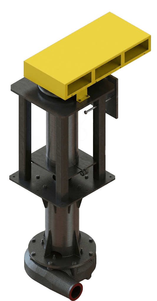
YPT DL SERIES — SUMP PUMPS
The DL Series is a vertical sump pump platform designed for abrasive, solids-laden slurries where simplicity and reliability are more valuable than complex auxiliary systems.
It is typically applied in sumps, pits, and tank recesses where splash, intermittent inflow, and solids settlement can challenge conventional sealed pumps.
The design philosophy prioritizes minimal routine maintenance by removing seal chambers and sealing elements from the duty.
At the same time, the pump is configured to keep critical mechanical components away from the slurry zone to improve uptime.
Selection focuses on solids behavior, submergence length, and how the pump will be serviced on site.
It is typically applied in sumps, pits, and tank recesses where splash, intermittent inflow, and solids settlement can challenge conventional sealed pumps.
The design philosophy prioritizes minimal routine maintenance by removing seal chambers and sealing elements from the duty.
At the same time, the pump is configured to keep critical mechanical components away from the slurry zone to improve uptime.
Selection focuses on solids behavior, submergence length, and how the pump will be serviced on site.
Reliable sump transfer in abrasive conditions
Typical duties
DL sump pumps are commonly installed where slurry collects naturally and needs to be transferred without adding sealing-water utilities or complex seal support.

These duties are often harsh because solids can settle, re-suspend, and change concentration depending on upstream operation and sump level.
In many plants, sump services are “hidden criticals” because they control housekeeping, spill recovery, and stable recirculation in key areas.
Operators also value predictable start-up behavior, especially when the duty is intermittent or the sump level fluctuates through a shift.
DL is therefore positioned for typical sump and pit services handling abrasive and solids-laden slurries.
In many plants, sump services are “hidden criticals” because they control housekeeping, spill recovery, and stable recirculation in key areas.
Operators also value predictable start-up behavior, especially when the duty is intermittent or the sump level fluctuates through a shift.
DL is therefore positioned for typical sump and pit services handling abrasive and solids-laden slurries.
Seal-less architecture to reduce failure points
Core design features
The DL Series is built around a “keep it simple, keep it clean” philosophy for sump duty. In abrasive environments, seals and seal chambers often become the first reliability bottleneck, so DL removes that dependency and reduces the number of slurry-sensitive interfaces.
Mechanical integrity is protected by keeping the bearing assembly positioned above the liquid level, so it operates away from contamination risk and splash exposure.
This layout also supports easier inspection and more predictable bearing life in dirty service. The overall intention is a sump pump that tolerates real plant variability while remaining straightforward to maintain.
Mechanical integrity is protected by keeping the bearing assembly positioned above the liquid level, so it operates away from contamination risk and splash exposure.
This layout also supports easier inspection and more predictable bearing life in dirty service. The overall intention is a sump pump that tolerates real plant variability while remaining straightforward to maintain.

Keep bearings clean, keep slurry moving
Principle of Operation
DL is designed to move slurry from a sump while keeping critical rotating and support components out of the slurry zone. Because the pump is seal-less, it avoids seal chambers and sealing elements that would otherwise require flushing, adjustment, and frequent attention in abrasive service.
The bearing assembly is located above the liquid level so it can run independently and remain free from slurry contamination during normal operation.
For service work, a secondary shaft arrangement supports easier impeller replacement without exposing the main shaft to unnecessary wear or damage.
The impeller is mounted at a 45-degree interface and secured by a seal-tight fastener concept, supporting safe operation even if motor rotation is reversed.
The bearing assembly is located above the liquid level so it can run independently and remain free from slurry contamination during normal operation.
For service work, a secondary shaft arrangement supports easier impeller replacement without exposing the main shaft to unnecessary wear or damage.
The impeller is mounted at a 45-degree interface and secured by a seal-tight fastener concept, supporting safe operation even if motor rotation is reversed.
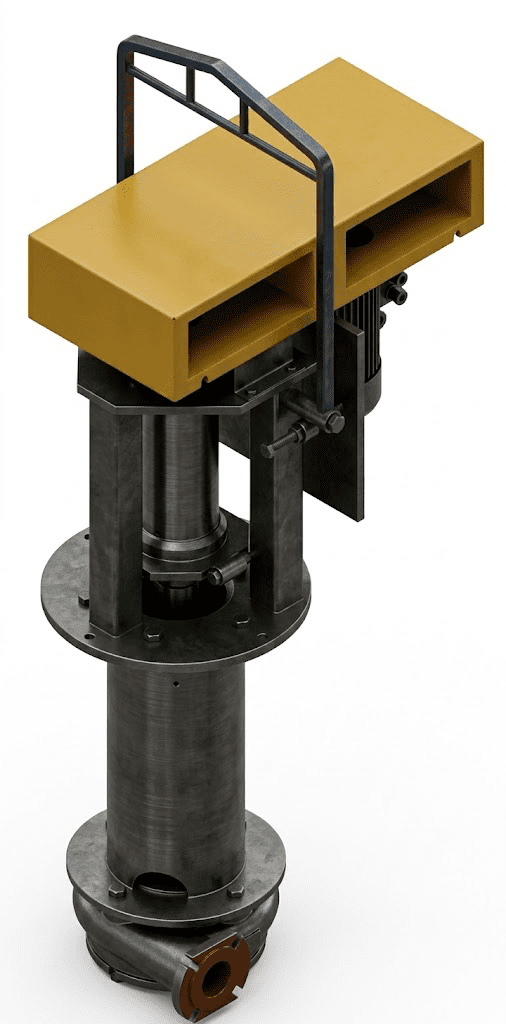

Choose semi-open or vortex for the risk
Impeller options & configurations
Sump duties are not all the same, so DL is offered with impeller configurations matched to solids behavior and operating pattern.
The standard DL configuration uses a semi-open impeller concept that supports strong solids handling and is less sensitive to air-related issues during intermittent operation.
Where clogging risk dominates—especially with fibrous or coarse solids—vortex-style impellers are often preferred because they maintain flow with larger internal clearances and reduced blockage tendency. For specialized duties, induced vortex designs can be applied where media protection or low attrition is important for the process.
The right choice depends on what the sump actually receives: coarse solids, fibrous material, aerated liquid, or relatively clean slurry with pressure/efficiency priorities.
The standard DL configuration uses a semi-open impeller concept that supports strong solids handling and is less sensitive to air-related issues during intermittent operation.
Where clogging risk dominates—especially with fibrous or coarse solids—vortex-style impellers are often preferred because they maintain flow with larger internal clearances and reduced blockage tendency. For specialized duties, induced vortex designs can be applied where media protection or low attrition is important for the process.
The right choice depends on what the sump actually receives: coarse solids, fibrous material, aerated liquid, or relatively clean slurry with pressure/efficiency priorities.
Hard-metal wear strategy for sump variability
Wet-end & wear material
In sump duty, wear can accelerate quickly because solids concentration may spike and local turbulence can increase as levels change.
DL follows a hard-metal wear philosophy for abrasive services, supporting predictable erosion resistance where elastomer solutions may be less suitable.
Standardizing wear material helps simplify spares, rebuild planning, and site training, especially when multiple sump pumps are installed across a plant.
Even with robust wear materials, wear life still depends strongly on operating speed, sump solids behavior, and how often the pump runs near low submergence.
The best lifecycle cost is achieved by matching the wear package to the expected extremes and then operating within a defined duty window.
DL follows a hard-metal wear philosophy for abrasive services, supporting predictable erosion resistance where elastomer solutions may be less suitable.
Standardizing wear material helps simplify spares, rebuild planning, and site training, especially when multiple sump pumps are installed across a plant.
Even with robust wear materials, wear life still depends strongly on operating speed, sump solids behavior, and how often the pump runs near low submergence.
The best lifecycle cost is achieved by matching the wear package to the expected extremes and then operating within a defined duty window.


Models & outline dimensions
Sump pumps must be selected with geometry first, because submergence length, floor clearance, and lifting access often control what will actually fit and be serviceable.
DL configurations are typically defined by outlet size and shaft/column length so the wet end sits at the correct depth while the drive and bearings remain accessible above.
For layout engineering, dimensions are useful not only for footprint planning, but also for platform height, guardrails, and safe maintenance handling.
Weight is a practical parameter for crane selection and for determining whether local lifting beams are required in the pump area.
Use the table below as a starting point for layout and access planning, then confirm final GA details with your motor/base and site constraints.
DL configurations are typically defined by outlet size and shaft/column length so the wet end sits at the correct depth while the drive and bearings remain accessible above.
For layout engineering, dimensions are useful not only for footprint planning, but also for platform height, guardrails, and safe maintenance handling.
Weight is a practical parameter for crane selection and for determining whether local lifting beams are required in the pump area.
Use the table below as a starting point for layout and access planning, then confirm final GA details with your motor/base and site constraints.
Model | Length | H1 | H2 | D | Weight |
|---|---|---|---|---|---|
DL80 | L80 | 800 | 870 | 530 | 415 |
DL80 | L120 | 1200 | 870 | 530 | 530 |
DL80 | L150 | 1500 | 870 | 530 | 565 |
DL80 | L180 | 1800 | 870 | 530 | 600 |
RFQ / sizing inputs
A correct DL selection is driven by the sump reality: level swings, solids variability, and the way the pump is started and stopped.
Two duties with the same average flow can require different configurations if one sump receives coarse solids and the other receives aerated or fibrous material.
Submergence and minimum level are especially important because they influence stability, wear rate, and the practicality of the installation.
It is also critical to define how the discharge line behaves, because backpressure and routing can change the operating point and affect reliability.
With the inputs below, the pump can be sized with realistic margins and the configuration can be locked faster for drawings, spares, and commissioning.